The layout of the turbocharger in a given application is critical to a properly performing system. Intake and exhaust plumbing is often driven primarily by packaging constraints. We will explore exhaust manifolds in more detail in subsequent tutorials; however, it is important to understand the need for a compressor bypass valve (commonly referred to as a Blow-Off valve) on the intake tract and a Wastegates for the exhaust flow.
Other Components
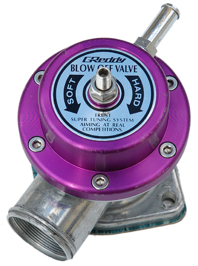
Blow-Off (Bypass) Valves
The Blow-Off valve (BOV) is a pressure relief device on the intake tract to prevent the turbos compressor from going into surge. The BOV should be installed between the compressor discharge and the throttle body, preferably downstream of the charge air cooler (if equipped). When the throttle is closed rapidly, the airflow is quickly reduced, causing flow instability and pressure fluctuations. These rapidly cycling pressure fluctuations are the audible evidence of surge. Surge can eventually lead to thrust bearing failure due to the high loads associated with it.
Blow-Off valves use a combination of manifold pressure signal and spring force to detect when the throttle is closed. When the throttle is closed rapidly, the BOV vents boost in the intake tract to atmosphere to relieve the pressure; helping to eliminate the phenomenon of surge.


Wastegates
On the exhaust side, a Wastegate provides us a means to control the boost pressure of the engine. Some commercial diesel applications do not use Wastegates at all. This type of system is called a free-floating turbocharger.
However, the vast majority of gasoline performance applications require a Wastegate. There are two (2) configurations of Wastegates, internal or external. Both internal and external Wastegates provide a means to bypass exhaust flow from the turbine wheel. Bypassing this energy (e.g. exhaust flow) reduces the power driving the turbine wheel to match the power required for a given boost level. Similar to the BOV, the Wastegate uses boost pressure and spring force to regulate the flow bypassing the turbine.
Internal Wastegates are built into the turbine housing and consist of a flapper valve, crank arm, rod end, and pneumatic actuator. It is important to connect this actuator only to boost pressure; i.e. it is not designed to handle vacuum and as such should not be referenced to an intake manifold.

External Wastegates are added to the exhaust plumbing on the exhaust manifold or header. The advantage of an external Wastegates is that the bypassed flow can be reintroduced into the exhaust stream further downstream of the turbine. This tends to
improve the turbines performance. On racing applications, this Wastegated exhaust flow can be vented directly to atmosphere.


